
This is an old revision of the document!
Table of Contents
Tracing Options
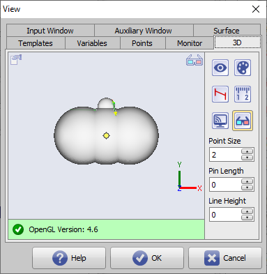
Using the [Options] button in the panel, you can make various settings on individual tabs with regard to graphics overlays on 2D and 3D image windows.
Tab |3D|
[Click on tab opens related wiki page]
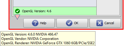
Status bar
The status bar in the 3D-View shows the suitability of the graphics card used for 3D rendering and the actuality of the installed OpenGL drivers. On MouseOver additional details are shown in the Hint.
Icon button [3D view]
The [3D View] icon button can be used to switch between 4 different graphics modes for displaying all 3D views at the local workstation provided that the graphics hardware and driver software used supports the selected display mode.

- Version 0: Slow / Color: Standard
- Version 1: Fast / Color: Standard
- Version 2: Fast / Color: Material
- Version 3: Fast / Color: Material + Shadow¹
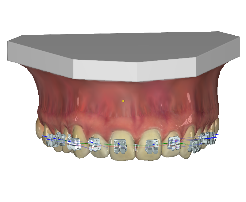
| Version 0 | Version 1 |
|---|---|
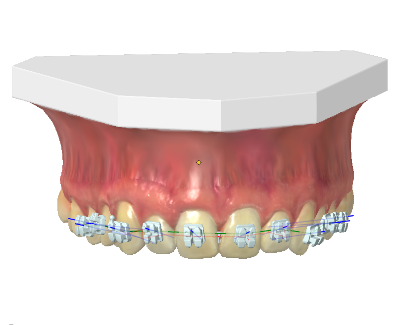 |  |
| Slow / Color: default | Fast / Color: default |
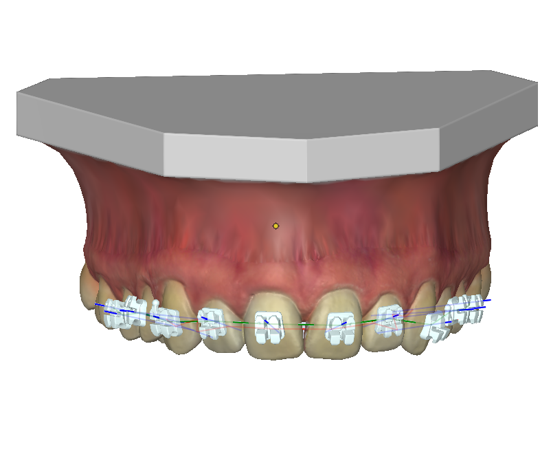
| Version 2 | Version 3 |
 | 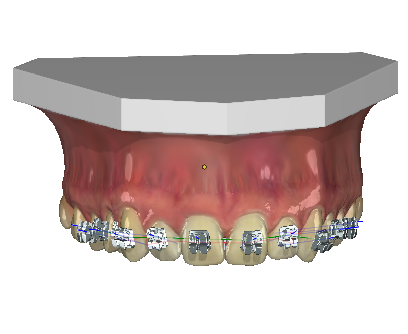 |
| Fast / Color: Material | Fast / Color: Material + Shadow |
¹ If possible the powerful Version 3 should be used. View properties like
- Highlights
- Brightness
- Blur
can be additionally adjusted in Panel View Options and also assigned module-specifically (system-wide for all workstations!).
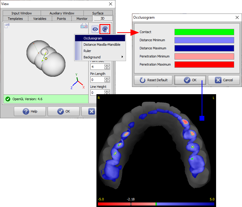
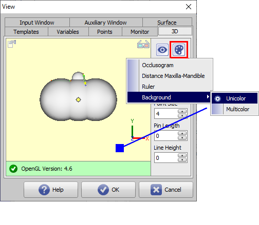
Icon key [Colors]
The [Colors] icon button can be used to make settings for

- Occlogram shades
- Spacing colors upper jaw-lower jaw
- Ruler color
- Background colors 3D view
- Monochrome
- Multicolor
• Occlogram colors
The colors used in the Occlusogram panel for occlusal crown distances can be set here. The default applies to all occlogram windows (all modules) in the workstation.
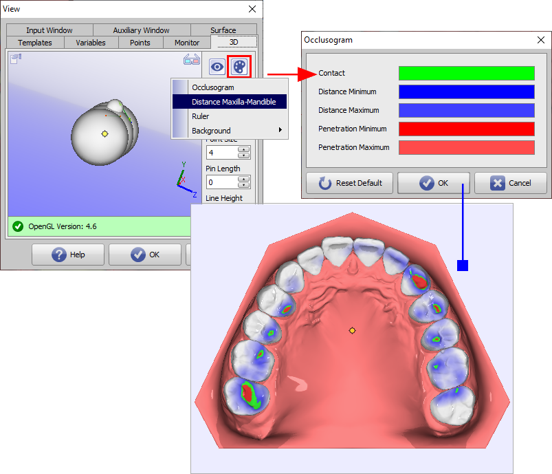
• Upper jaw-lower jaw spacing colors
The colors used on the segmented crown for occlusal crown spacing can be set here. The default applies to the Aligner 3D and V.T.O.3D modules at the workstation.
• Ruler color
Here you can set the color of the optional ruler displayed in the 3D-View. The default applies to the modules at the workstation.

• Background color 3D-View
Here you can set the background for 3D-Views. The default applies to all 3D views on the workspace except image preview on main window tab |images / 3D data| and full screen views.

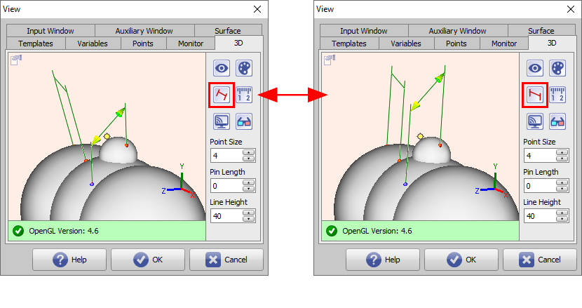
Icon-Taste [Linien senkrecht | automatisch ausrichten]
Mit der Taste [Linien …] kann vorgegeben werden, ob Messlinien parallel zum Objektkoordinatensystem oder senkrecht zur jeweiligen Bezugsebene gezeichnet werden sollen.
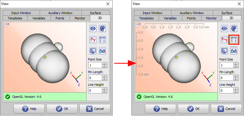
Icon-Taste [Skala anzeigen]
Mit der [Lineal]-Taste wird die Anzeige eines horizontalen und vertikalen Lineals in der über Taste [Farben] eingestellten Linealfarbe innerhalb des 3D-Views gesteuert. Die Einstellung gilt am Arbeitsplatz und für alle 3D-Views außer für die Vollbildansichten.
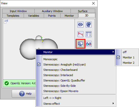
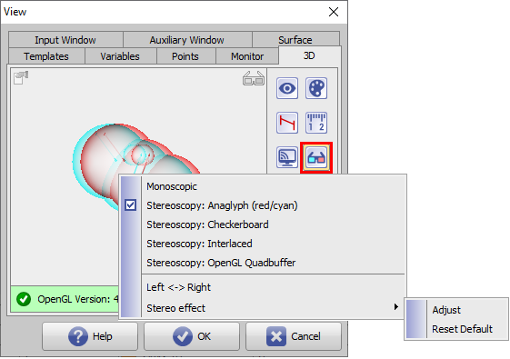
Icon-Taste [View Mirror]
Über Taste [View] wird festgelegt, ob das aktive 3D-Fenster auf einem separaten Monitor im Vollbild angezeigt und welche Darstellungsart hierfür (wenn hardwareseitig unterstützt) verwendet werden soll:
- Monoskopisch
- Stereoskopie: Anaglyph (Rot/Cyan)
- Stereoskopie: Checkerboard
- Stereoskopie: Interlaced
- Stereoskopie: OpenGL Quadpuffer
- Stereoskopie: Side-by-Side
- Stereoskopie: Epson Moverio
Zusätzlich kann bei Auswahl einer stereoskopischen Darstellung der Stereoeffekt mittels Schieberegler angepasst oder auf Standard zurückgesetzt werden.
Icon-Taste [Stereoskopie]
Über Taste [Stereoskopie] wird eingestellt, welche Darstellungsart für das aktive 3D-Fenster (wenn hardwareseitig unterstützt) verwendet werden soll:
- Monoskopisch
- Stereoskopie: Anaglyph (Rot/Cyan)
- Stereoskopie: Checkerboard
- Stereoskopie: Interlaced
- Stereoskopie: OpenGL Quadpuffer
Zusätzlich kann bei Auswahl einer stereoskopischen Darstellung der Stereoeffekt mittels Schieberegler angepasst oder auf Standard zurückgesetzt werden.
Hinweis:
Der gewählte Stereo-Mode wird im 3D-View über das oben rechts angezeigte Stereo-Icon aktiviert und deaktiviert.
| Stereomode inaktiv | Stereomode aktiv |
|---|---|
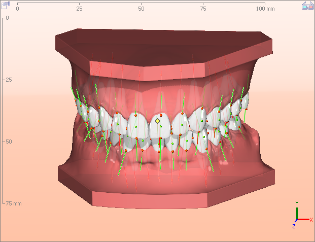 | 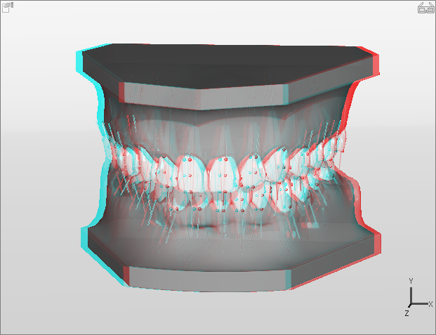 |
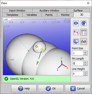
Weitere Einstellungen
Zusätzlich können auf Reiter |3D| noch Einstellungen zu
- Punktgröße
- Pin-Länge
- Linienhöhe
vorgegeben werden.
• Punktgröße
Parameter [Punktgröße] steuert den Radius des als 3D-Kugel dargestellten Messpunktes im 3D-View zwischen 1 und 40..
• Pin-Länge
Parameter [Pin-Länge] steuert den Abstand eines als 3D-Kugel dargestellten Messpunktes von seiner Position auf der jeweiligen Oberfläche zwischen 0 und 40.
• Linienhöhe
Parameter [Linienhöhe] stereur den Abstand von Bemaßungen zwischen 0 und 40.
 | 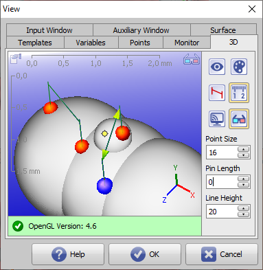 |
| (PSPL/LH) = (1,0,0) | (PSPL/LH) = (16,0,20) |
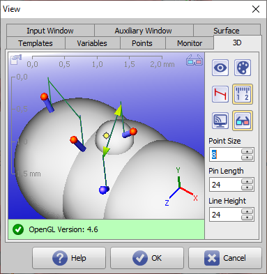 |  |
| (PSPL/LH) = (8,24,24) | (PSPL/LH) = (4,40,20) |