This is an old revision of the document!

(remove this paragraph once the translation is finished)
Calibration of 2D Images
To perform metric meaurements on 2D images, the real size of the image content to be measured has to be known. The following description for the measurement calibration of lateral ceph images may be applied also to any other 2D image in the same way.
The metric calibration of a 2D image for measuring purposes is usually done by means of a reference line which is part of the image content itself while its real length is known in relation to the image content to be analyzed.
dependig on the type of reference line, for a correct calibration specific sdettings are required. These settings are specific for each image type and are saved for the actual workstation resp. the use Windows login.
Case 1: Reference Plane equal to Measuring Plane
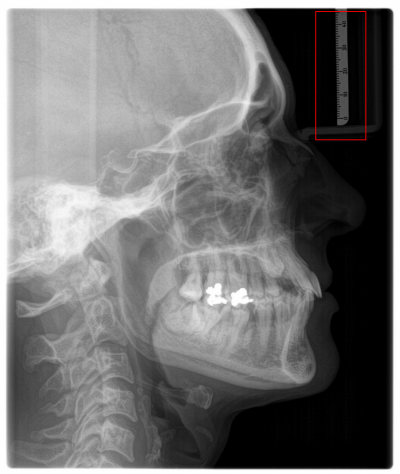
Relatively common, in lateral ceph images a ruler mounted onto the nose fixature of the xRay device is available. In such cases, the calibration of the reference line (the ruler) is identically to the calibration for the measuring plane.
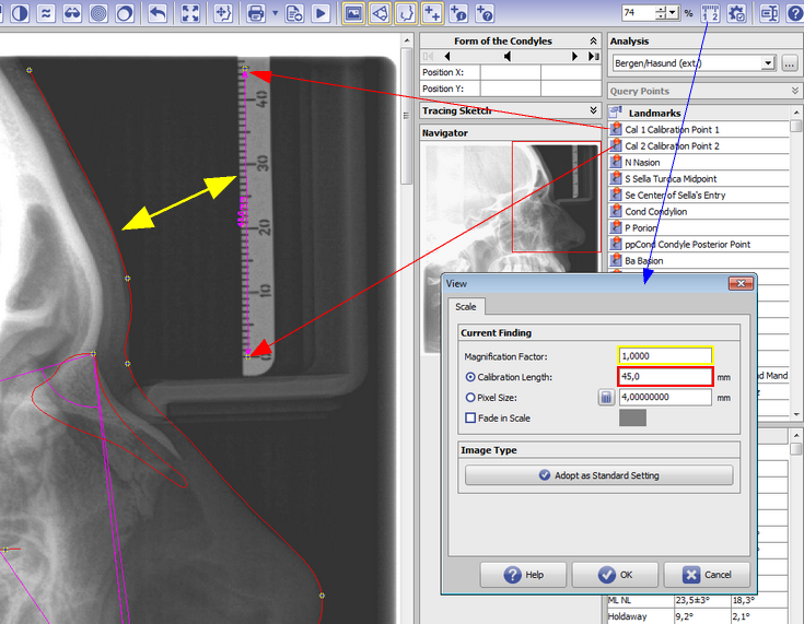
To be able to use the reference line calibration for cephalometric measurements within the lateral ceph image, calibration landmarks Cal 1 and Cal 2 have to be digitized over begin end end position of a known distance within the reference (in the example below: Cal 1 on scale line 0mm and Cal 2 on scale line 45mm - regardless which order).
The real metric difference between both of these landmarks must be filled in as Calibration Length in dialog Scale.
For Magnification Factor the value 1,0 has to be used b/c the ratio between measuring plane and ruler metric is identical.
If these calibration settings should be used for the future import of lateral ceph images on this workstation, this can be set up by button [Adopt as Standard Setting].
Case 2: Reference Plane not equal to Measuring Plane
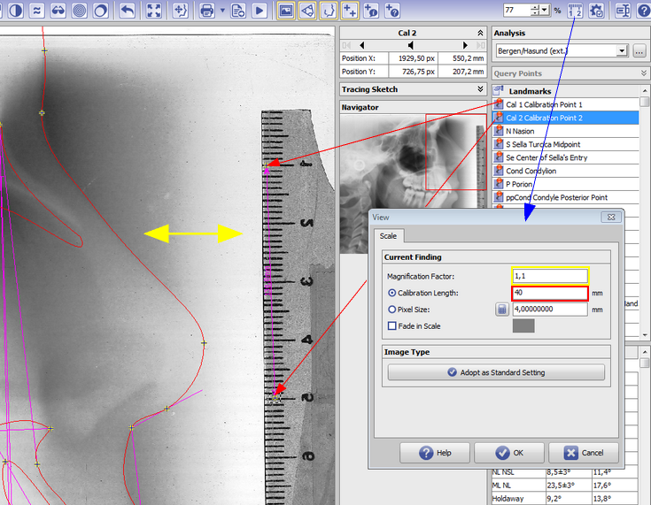
Manchmal ist im digitalisierten FRS ein Maßstab (Lineal) abgebildet, dessen Metrik aber nicht für die sagittale Schädelmitte gilt. Das trifft z.B. zu, wenn Positivfolien von analogen Röntgengeräten mit aufgelegtem Lineal gescannt wurden. In diesen Fällen besteht zwischen dem Lineal und dem FRS ein Größenunterschied, der durch die Strahlenoptik zwischen Quelle, Patient und Detektorebene des verwendeten Röntgengerätes bestimmt wird und meist mit etwas 110% abgeschätzt wird.
Um die Kalibrierung der Referenzstrecke für die Vermessung des FRS nutzen zu können, müssen die beiden Normierungspunkte Norm A und Norm B auf Anfangs- und Endpunkt eines bekannten Abstandes innerhalb der Referenz gesetzt werden (im Bild Norm A = Teilstrich 10mm und Norm B = Teilstrich 50mm - egal in welcher Reihenfolge).
Die reale metrische Differenz zwischen diesen beiden Punkten muss im Dialog Maßstab als Normlänge eingetragen werden.
For Magnification Factor the ratio between measuring plane and ruler metric has to be used.
If these calibration settings should be used for the future import of lateral ceph images on this workstation, this can be set up by button [Adopt as Standard Setting].
Case 3: No Reference Line available
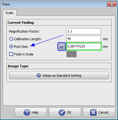
Ist im Bild keine Referenzstrecke vorhanden, ist eine metrische Auswertung nicht möglich. Die Kalibrierung kann von einem Referenzbild mit bekannter Kalibrierung übernomen werden, welches unter den selben Bedingungen aufgezeichet wurde. Hierzu muss die sog. Pixelgröße für das Referenzbild ermittelt und auf das auszuwertende Bild übertragen werden.
Die Berechnung der Pixelgröße für das Referenzbild unter Verwendung der voreingestellten korrekten Werte für Maßstab und Normlänge erfolgt im Dialog Maßstab, indem die Auswahl auf Pixelgröße umgestellt und mit Klick auf das Taschenrechner-Icon der Wert errechnet und angezeigt wird.
Diese Einstellungen müssen im Anschluss identisch in den Dialog Maßstab des auszuwetenden Bildes übertragen werden.
If these calibration settings should be used for the future import of lateral ceph images on this workstation, this can be set up by button [Adopt as Standard Setting].
| Note |
|---|
| Such unique calibration for the whole image content is only correct if the image magnification factor is the same for each detail of the imaged structures. In fact, due to the scenography and the spatial dimension of the image content perpendicularly to the optical axis this requirement is not really fulfilled for many imaging systems (e.g. optical cameras). This is also true in a usually neglected extant for lateral ceph images and can be explained by the fact that even for a total symmetrical patient double contours will be imaged. Nevertheless, the same calibration is applied for all metric measurements although this is only exact for the mid-sagittal skull plane. |


