
Table of Contents
Workflow 3D Export
Note:
In program versions OnyxCeph³™ BASIC and 3D PRO, only 3D objects of type maxilla and mandible (w/o segmentation or modification) can be exported in open 3D formats. In program versions OnyxCeph³™ LAB and OMS, all 3D object types can be exported w/o limitations.
For the export of bracket bonding trays (IBT) designed in module Bonding Trays, a flat contact surface should be assigned.
Bracket Export:
The export of 3D bracket geometries is excluded by most bracket manufacturers as part of the confidential agreement for the CAD files for IP protection reasons.
Open Export Window
To export a single 3D object or a series of steps, the 3D export window has to be opened either by icon button [Export Data] or from the context menu of panel Object List.
The export of a single finding can also be launched from the Thumbnail context menu on main window tab |Images / 3D Data|.


Icon Bar

 ¹
¹
- Switch to previous step¹
- Reload
- Step number increment for labeling¹
- Switch to next step¹
- Show maxilla only
- Show mandible only
- Swich 3D views
- Fabrication ordes (if configured)
- Reload export settings
- Save export settings
- Help on 3D export
¹ Only when export is launched in module Aligner 3D
Panel Object List

Lists all 3D objects which have been visible in the module window. Selection can be modified using the list context menu. Note that all active (displayed) objects will be exported by button [Export].
If maxilla and mandible objects are activated side-by-side at the time of export, the user will be asked by a message if both jaws should be exported to separate files.
Panel Inspect
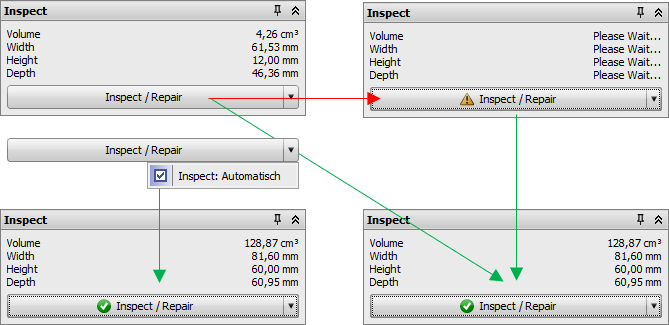
The panel provides some metric measurements for the selected objects.
In addition, there is an [Inspect/ Repair] button with a context menu. If context menu option [Inspect: Automatically] is selected, the dataset mesh will be topologically inspected and repaired if needed automatically and the green [OK] icon will appear in front of the caption after successfully done. Since the inspect / repair process requires additional memory, the option should be deselected if such action is not required for sure.
If option [Inspect: Automatically] is deselected, no icon will initially be displayed in front of the button caption and the user can start the inspection process manually. In case no mesh problem is found, the green [OK] icon will be displayed. Otherwise, the yellow [Warning] icon comes up. In such case, the repair process can be launched manually thereafter.
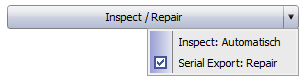
Option [Serial Export: Repair] is only available if the 3D export is opened in module Aligner 3D. It activates the repair process for each single aligner step export.
Panel Trim
Panel Trim allows to trim the objects in all directions by adjustable clipping planes. By selection lists [Align], the selected trim planes are transformed to 0 with their vertical component. The selected orientation is applied thereafter.
The [Horseshoe-Shaped Based] checkbox (as of Releases > 3.2.185) enables trimming with a trim line automatically calculated on the basis of the gingiva boarder and vertical filling of the distance to the set trim plane as a horseshoe base. This can be helpful if the set trim planes collide with the surfaces of a standard base tray or if attaching a base tray has been forgotten in principle.

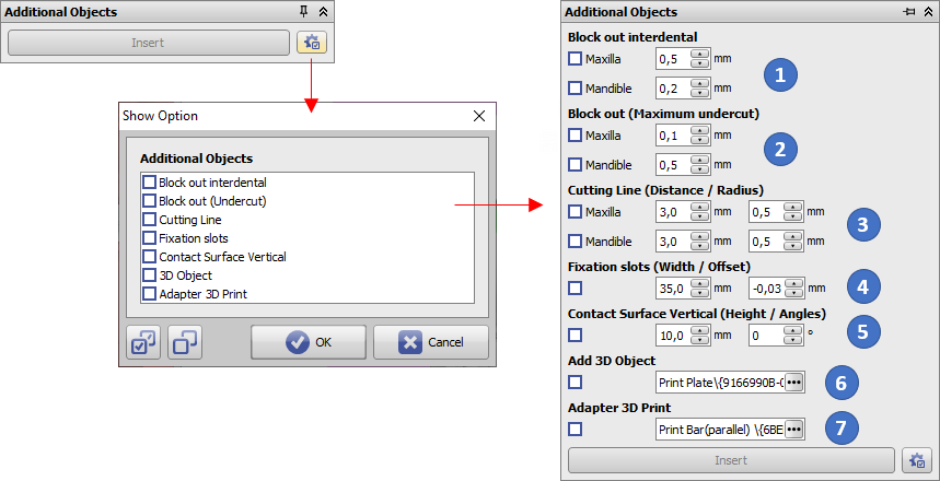
Panel Additional Objects
The panel allows to add additional objects during export. All but the first option is hidden by default and can be enabled by the configuration button:
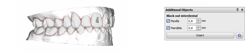
- A defined amount of support can be filled in between the teeth of the upper and lower arch
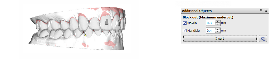
- A defined amount of support can be filled in to avoid vertical undercuts in upper and lower arch
- Cutting lines for trimming the aligner after thermoforming
- Fixation slots for Hinz-Pins to reposition occlusion
- A posterior support surface of the set height is added for [both jaw] objects at the preset angle relative to the occlusal plane or (if active) to the section plane used at a distance that ensures complete coverage of the posterior end.
- Objects from the user defined 3D object library linked to the assigned jaw and relative to the common 3D coordinate system not regarding trimming planes, e.g. for fixator adapters
- Objects from the user defined 3D object library linked to the assigned jaw and relative to the common 3D coordinate system regarding (green) trimming planes, e.g. for coordinate system adapters for trimming/manufacturing
Option 1: Block out interdental
Option 2: Block out (Undercut)
Option 3: Cutting Line
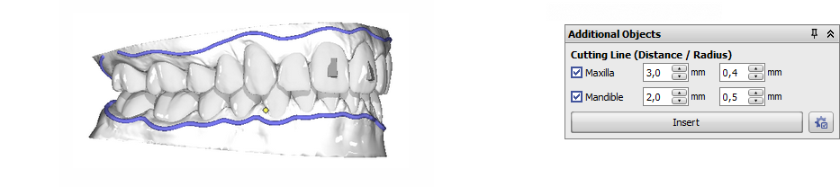
The trim line position (gingiva distance) is pre-defined but can be customized if option Cutting Line is activated n module Aligner 3D.
Option 4: Fixation slots
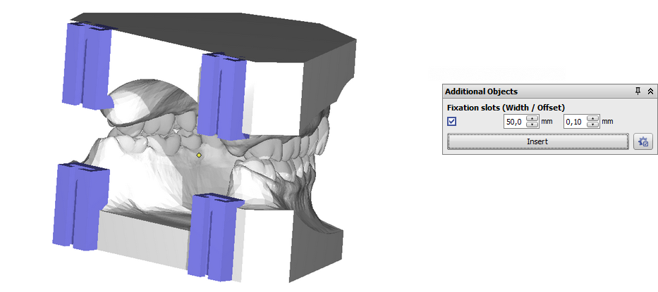
The object position is predefined in vertical and transversal direction. The horizontal position refers to the position of the rear trim plane after cutting. The transversal distance can be modified via the [Distance] input field. In addition, parameter [Offset] can be used to widen or narrow the guide to achieve a better fit of the Pins.
Option 5: Contact Surface Vertical
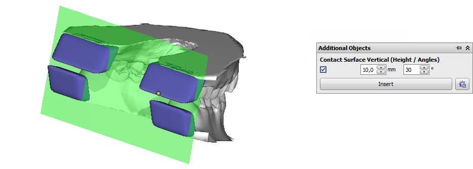
The [Contact Surface Vertical] option can be used if [tilted] support is required for vertical printing.
Option 6: 3D Object
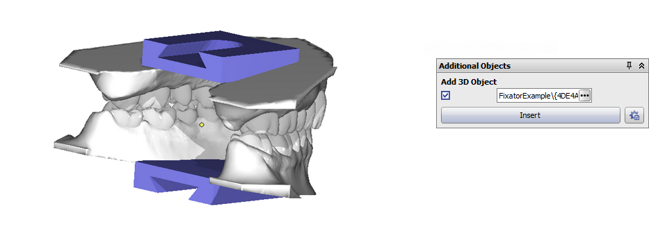
The object position is taken over from the object orientation in the 3d object library. Trim planes will not influence the position of the 3D object in relation to the model. See example Add Occlusal Pins.
Option 7: Adapter 3D Print
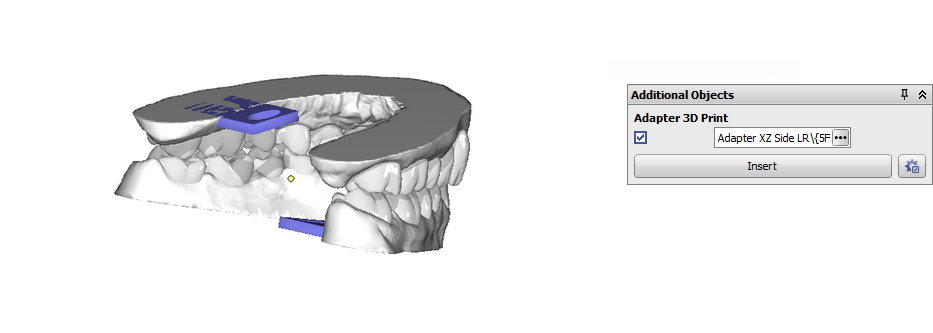
In-plane navigator arrows will be displayed to modify the object position in relation to the trim plane which is aligned itself to the object orientation in the 3d object library.
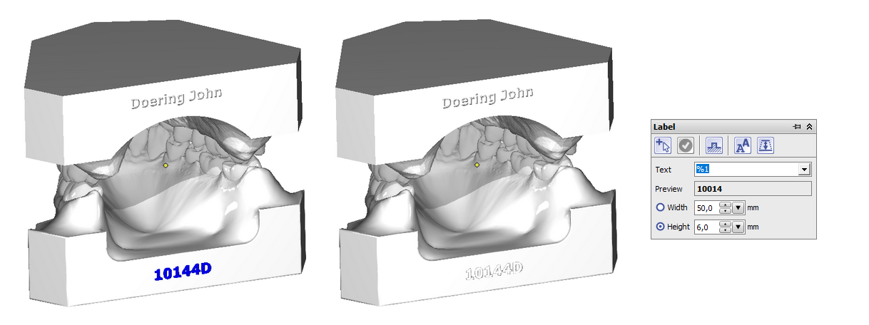
Panel Label
Allows to put labels onto the object surface by right click before export. Labels can be created with different parameters for text width, height and decoration. Labels can use plain text or space holders, e.g.
- %1 → Patient ID
- %2 → Name
- %3 → First Name
- %4 → Date of birth format YYYYMMDD
- %5 → Gender
- %A → Model number
- %D → Social insurance number
- %S → Step number (only if launched in module Aligner 3D)
- %X → TimeStamp YYYYMMDDHHMMSS
It is recommended to define label Height instead of Width to make sure same metric font size for different text lengths. The labels are displayed in edit mode (blue) first to allow modifications but must finally be inserted by button [✔].
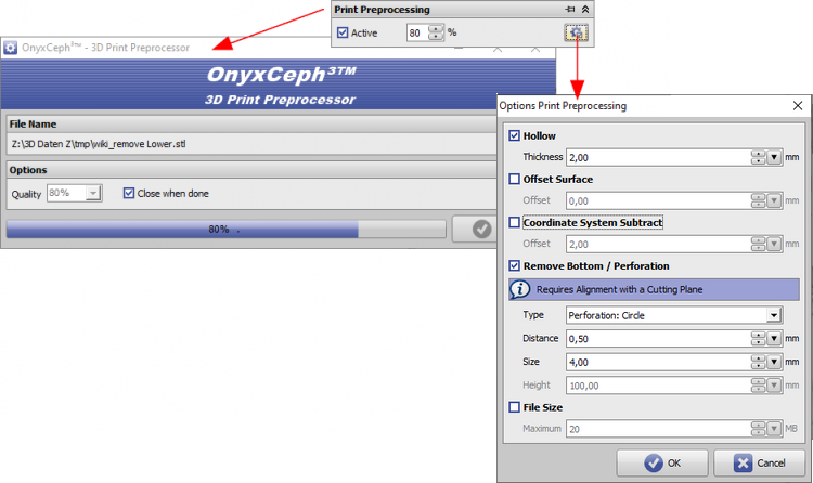
Panel Print Preprocessing
By using the option Print Processing, the dataset can be re-meshed into a single surface before export. This can be helpful in cases where the manufacturing device (e.g. the 3D printer) is not able to handle internal surfaces like roots or support material correctly.
The mesh size is controlled by the selected percentage (… 200%). Selecting about 70% results in an optimum for quality and file size in most of the cases.
By the panel menu button on the right, an Options window is displayed where additional features like
- Hollow
- Offset Surface
- Remove Bottom / Perforation
- File Size can be configured.
Several such export examples are described below.
Presetting a maximum [File Size] will reduce the final object file size by summarizing triangles in plane surface regions w/o influencing the geometrical object resolution.
Please note that most of the print preprocessing options refer to a reference plane. This must be defined and applied in panel Trim (e.g. planes Up and Down). In addition, this export alignment must be set to these trim planes in the same panel (e.g. selection [Upper/Lower]).
If print preprocessing is applied, all export processes run parallel as separate processes side by side - e.g. in serial export from module Aligner 3D.


| Examples |  |  |  |  |  |  |  |  |
|---|
See also: Options Print Preprocessing
As of releases 3.2.169, perforation [Cylinder] is also available:

As of releases 3.2.185, the perforation [Honeycomb] is also available:

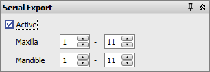
Panel Serial Export
This checkbox will only be available in module Aligner 3D. If it is activated, all selected treatment steps can be exported automatically as a series. All options (cutting, inserting support, labeling, print processing) have to be defined for one single step only (e.g., for the 1st one) to be applied the same way on all subsequent steps thereafter. If only a single jaw is visible, the sequence is exported only for this jaw, else it is exported and automatically labeled and named to separate files for maxilla and mandible.
Note: Checkbox [Select All] is only available if he Export window was opened from within module Aligner 3D.
Export Formats
OnyxCeph³™ supports export in 3D formats
- STL
- OBJ
- ZPR
- PLY
- OFF
- DXF
Note: If Option Print Preprocessing (re-meshing) is selected, only STL format is available.
IBT Export
If bracket bonding trays (IBT) should be manufactured by 3D printing technologies, one of the available design options fo a flat contact surface should be used in Module Bonding Trays to avoid additional support for printing.

For production by service provider Dreve, such a flat contact surface is required.
From 10/2023 until further notice please use option Print Preprocessing with 120% (without other parameters).